


Description
This Application Note explains how to obtain tilt measurements from an electrolytic tilt sensor and signal conditioner. It covers schematics and code for each protocol available on signal conditioners from The Fredericks Company. All examples will show code and circuits with an Arduino Uno, so there will be differences in code when using other platforms. Each example will provide a raw output from the sensor in a variety of units. Any of these units can be converted to degrees using the methods explained in Application Note 1005.
Analog
Both the 1-6200-007 and 1-6200-012 signal conditioners have analog outputs. On the 1-6200-007, both axes and the temperature are output from pins XA, YA, and T respectively. Connecting to the Arduino requires direct connections from the signal conditioner to the analog input pins of the Arduino. 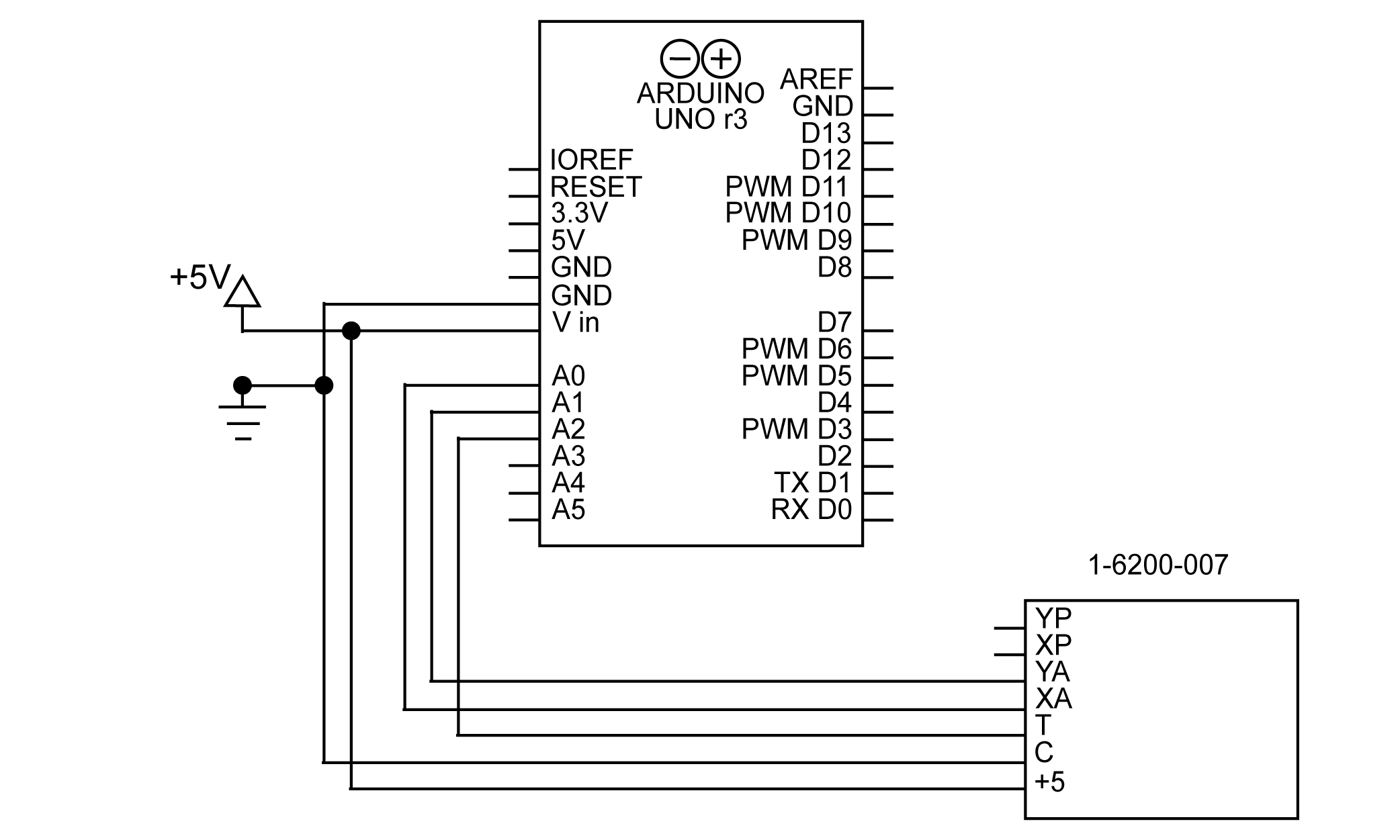
Figure 1 Schematic for connecting 1-6200-007 to Arduino using analog
Note that the 1-6200-012 signal conditioner does not have an analog temperature output, so temperature must be read using RS-232. See the section on RS-232 for more information on reading temperature from the 1-6200-012.
With the circuit assembled the data can be read using the Arduino’s analogRead() function. An example of this is shown below:
x = analogRead(A0);
y = analogRead(A1);
temperature = analogRead(A2);
The result of this code will be a raw value that represents the voltage on the analog pins. The resolution of this measurement will be dependent on the hardware used to read the voltage; on an Arduino Uno, the analog pins have a resolution of 10 bits.
PWM
PWM measurements are available on the 1-6200-007 signal conditioner. With PWM, the x and y tilt angles can be read from the digital XP and YP pins on the signal conditioner. There is no temperature PWM output, so that will have to be read from the analog pin. A schematic for this setup is shown in figure 2. 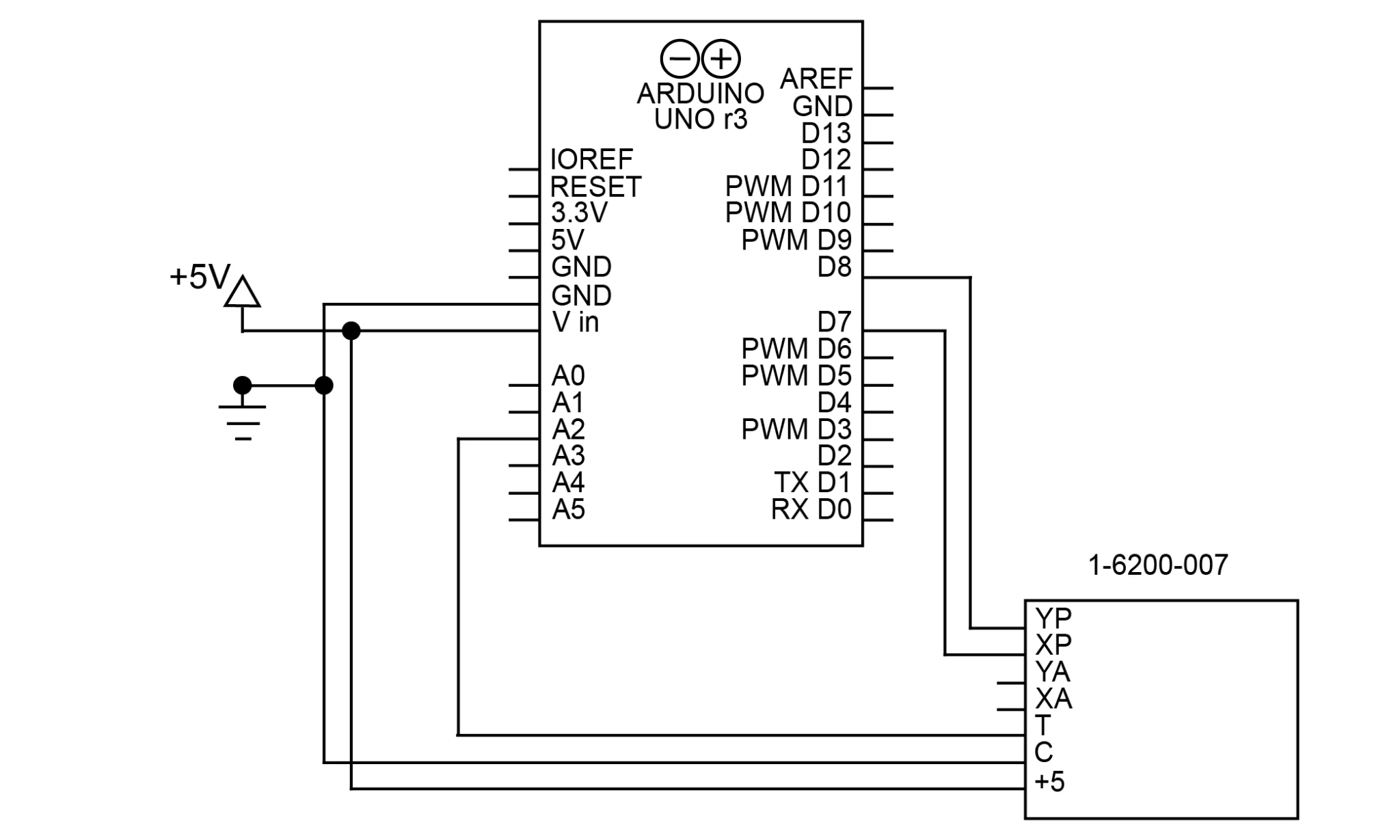
Figure 2 Schematic for connecting 1-6200-007 to Arduino using PWM
Note that the PWM outputs can be attached to any digital pins on the Arduino, not just the PWM pins. In this example, pins D7 and D8 are used, both non-PWM pins.
Reading a PWM signal with an Arduino is best done with the pulseIn() function. The pulseIn() function will time how long a pulse lasts in either the high or low state. In this case, we will time the high state.
x = pulseIn(XPIN, HIGH);
y = pulseIn(YPIN, HIGH);
temperature = analogRead(A0);

char res[50];
sprintf(res, "X: %i, Y: %i, Temperature: %i", x, y, temperature);
Serial.println(res)
The result will be the length of the pulse in microseconds. The pulseIn() function can read pulses as short as 10 µs, meaning its measurement of the up to 8ms pulse will have an accuracy similar to a 10-bit output. This accuracy will be higher if the device reading it can detect smaller pulses.
SPI
SPI is a synchronous serial communication protocol available on the 1-6200-005 signal conditioner. The protocol works on a master/slave technique using 4 connections: MISO (Master In Slave Out), MOSI (Master Out Slave In), CLK (Serial Clock), and SS (Slave Select). The master will send commands to the slave over MOSI (labeled IN on the 1-6200-005), and the slave will respond over MISO (labeled OUT on the 1-6200-005). CLK is a clock created by the master that synchronizes the slave’s communication. SS is used to enable a slave; this pin is how SPI supports multiple devices on one bus (see the “SPI Bus” section for more info).
The Arduino Uno has predefined pins for the MOSI, MISO, and CL. These are shown in the following table:
| MOSI | D11 |
| MISO | D12 |
| CLK | D13 |
The schematic for connecting these to the Arduino is shown in figure 3. 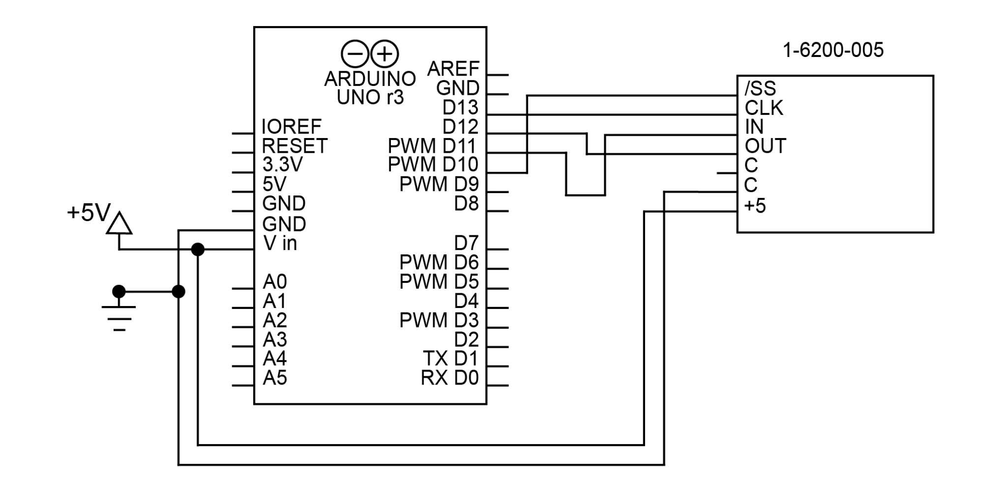
Figure 3 Schematic for connecting 1-6200-005 to Arduino with SPI
To communicate with the sensor, we will use Arduino’s SPI library. SPI.begin() will initialize the SPI library (however it will not open communications). Since this circuit only has one SPI device, pin 10 (SS) will be set to LOW, enabling the slave controlled by that pin. This will stay set to LOW for the entire program; there is no reason to disable the slave in this circuit.
void setup() {
    SPI.begin(); // initialize SPI
    digitalWrite(10, LOW); // enable slave 1
}
Now that we’ve initialized the library, we must open the connection with the signal conditioner. This is done using the SPI.beginTransaction() function. This function takes one argument, an SPISettings object. This object will provide all the necessary information to create the connection. The SPISettings object has three arguments:
- Maximum clock speed of the slave, which is 20Mhz on the 1-6200-005.
- The second argument determines whether the SPI interface will use Most Significant Bit or Least Significant Bit First. For the 1-6200-005 this is Most Significant Bit First (or MSBFIRST).
- The third argument determines the SPI mode; for the 1-6200-005, SPI mode 2 (CPOL=1, CPHA=0) is used.
// open SPI communication
SPI.beginTransaction(SPISettings(20000000, MSBFIRST, SPI_MODE2));
The SPI.transfer() function is used to send and receive data. It will simultaneously send the command and return whatever it reads from the MISO pin. Note that the slave will always take one clock cycle to respond; therefore, the result from each command will not be received until the next cycle. For example, in the code below, the function that sends the X axis low byte request returns the X axis high byte value because of this delay.
Note that the 0x39 command is essential to getting good measurements. This command tells the board to get a new measurement of tilt. In the code below, it is sent once in the beginning, and once again at the end of the if statement, where the low temperature bit is received.
    SPI.transfer(0x39); // update sensor data
    delay(1); // wait for SPI response
    res = SPI.transfer(0x31); // get status, request high x byte
    delay(1); // wait for SPI response

    if (res == 0x2A) { // verify sensor data updated successfully
        high = SPI.transfer(0x32); // get high x byte, request low x byte
        delay(1); // wait for SPI response
        low = SPI.transfer(0x33); // get low x byte, request high y byte
        x = (high << 8) | low; // merge low and high bytes into int

        delay(1); // wait for SPI response
        high = SPI.transfer(0x34); // get high y byte, request low y byte
        delay(1); // wait for SPI response
        low = SPI.transfer(0x35); // get low y byte, request high temperature byte
        y = (high << 8) | low; // merge low and high bytes into int

        delay(1); // wait for SPI response
        high = SPI.transfer(0x36); // get high temp byte, request low temp byte
        delay(1); // wait for SPI response
        low = SPI.transfer(0x39); // get low temperature byte, update sensor data
        temperature = (high << 8) | low; // merge low and high bytes into int
    }

    SPI.endTransaction(); // close the SPI communication
Note that the responses will be in separate high and low bytes. The code above converts these to 16-bit integers using the expression (high << 8) | low.
SPI Bus
It is also possible to connect 1-6200-005 signal conditioners together in an SPI bus. An SPI Bus allows all SPI devices to share the CLK, MISO, and MOSI connections. Each slave, however, gets its own SS connection, allowing the master to select which slave it wants to communicate with. The number of SPI devices you can use at once is limited by the number of independent SS connections you can make. Figure 4 shows the schematic for 2 sensors on an SPI bus with pins D9 and D10 used as the SS signals. 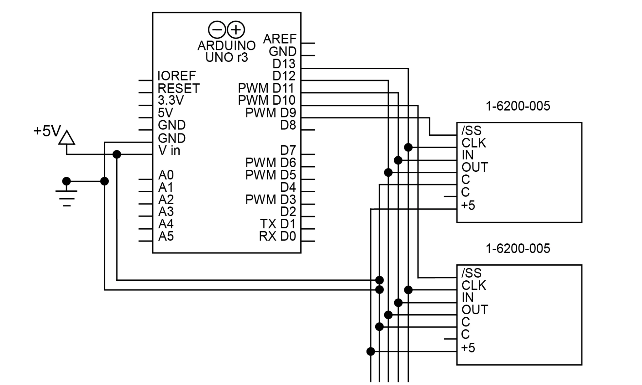
Figure 4 Schematic for connecting two 1-6200-005’s to Arduino with an SPI bus. Note the separate /SS connections for each device
This code is very similar to the code for the single SPI device; note that the SS pins are changed to control which slave is communicated with.
// open SPI communication

    SPI.beginTransaction(SPISettings(20000000, MSBFIRST, SPI_MODE2));
    digitalWrite(10, LOW); // enable the slave controlled by D10

    SPI.transfer(0x39); // request status
    delay(1);
    res = SPI.transfer(0x31); // get status, request high x byte
    delay(1);

    if (res == 0x2A) {
        hi = SPI.transfer(0x32); // get high x byte, request low x byte
        delay(1);
        lo = SPI.transfer(0x33); // get low x byte, request high y byte
        x = (hi << 8) | lo;

        delay(1);
        hi = SPI.transfer(0x34); // get high y byte, request low y byte
        delay(1);
        lo = SPI.transfer(0x35); // get low y byte, request high temperature byte
        y = (hi << 8) | lo;

        delay(1);
        hi = SPI.transfer(0x36); // get high temperature byte, request low temperature byte
        delay(1);
        lo = SPI.transfer(0x39); // get low temperature byte
        temperature = (hi << 8) | lo;
    }

    digitalWrite(10, HIGH); // disable the slave controlled by D10
    digitalWrite(9, LOW); // enable the slave controlled by D9

    SPI.transfer(0x39); // request status
    delay(1);
    res = SPI.transfer(0x31); // get status, request high x byte
    delay(1);

    if (res == 0x2A) {
        hi = SPI.transfer(0x32); // get high x byte, request low x byte
        delay(1);
        lo = SPI.transfer(0x33); // get low x byte, request high y byte
        x = (hi << 8) | lo;

        delay(1);
        hi = SPI.transfer(0x34); // get high y byte, request low y byte
        delay(1);
        lo = SPI.transfer(0x35); // get low y byte, request high temperature byte
        y = (hi << 8) | lo;

        delay(1);
        hi = SPI.transfer(0x36); // get high temperature byte, request low temperature byte
        delay(1);
        lo = SPI.transfer(0x39); // get low temperature byte
        temperature = (hi << 8) | lo;
    }

    digitalWrite(9, HIGH); // disable the slave controlled by D9
    SPI.endTransaction(); // close the SPI communication
Note that if 2 SPI slaves are enabled at the same time and a message is sent, the signals will interfere and the response will not be properly read.
RS-232
RS-232 (TIA-232) is a common serial communication protocol. A 3-wire version of RS-232 is available on both the 1-6200-006 and 1-6200-012 signal conditioners. Connecting RS-232 consists of connecting the grounds together, and connecting each Rx to the other device’s Tx.
In this application, we will use the Arduino’s SoftwareSerial library to create a virtual serial port to use. This library gives us the ability to invert the signals on the port, which is necessary to communicate with the sensor. It also keeps the hardware serial port available for other uses. To create the circuit for RS-232, simply connect D10 (our virtual RX pin) to OUT and D11 (our virtual TX) to IN. This is shown in figure 5. 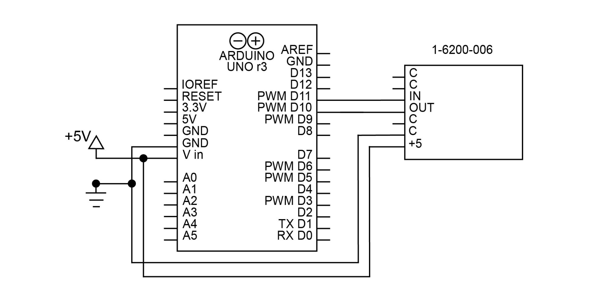
Figure 5 Schematic for connecting 1-6200-006 to Arduino with RS-232 and the SoftwareSerial library
Using SoftwareSerial, you can initialize the virtual serial port with the following code:
SoftwareSerial Sensor(10, 11, true); //RX, TX, inverse
void setup() {
    Sensor.begin(9600); //RX, TX, invert
}
Note that devices with UART TTL serial ports (like the Arduino) need an inverted serial connection, or it will not be able to communicate. With an Arduino, this is done with the third argument when creating the virtual serial port (“true” for an inverted signal).
To read tilt through RS-232, first, send the command for the data you want, then read the data from the port. The code to read the x axis, y axis, and temperature values is below:
Sensor.print('x'); // send command for x axis tilt
delay(50); // delay to give time for response
b = 0;
while (Sensor.available() != 0 && b < 8) {
    x[b++] = Sensor.read(); // read received bytes into char array
}

Sensor.print('y'); // send command for y axis tilt
delay(50);
b = 0;
while (Sensor.available() != 0 && b < 8) {
    y[b++] = Sensor.read();
}

Sensor.print('t'); // send command for temperature
delay(50);
b = 0;
while (Sensor.available() != 0 && b < 8) {
    temperature[b++] = Sensor.read();
}
The definitions of all RS-232 commands are available on the datasheet for the signal conditioner.
The response from this code will be an 8-byte character array, terminated by newline and carriage return characters (0x0a, 0x0d). This will not be a string, so it will most likely have to be converted to a string. If necessary, it can also be converted to an int.
// convert char array to string
    x[b - 2] = '\0';

    // convert string to 16-bit int
    xInt = atoi(x);
The code above replaces the newline character with the null character, terminating the string immediately after the last character. This requires using the b variable, so it will likely have to be done immediately after receiving the measurement. To achieve this without using the b variable, the termination character can also be placed at the end of the array, but this will leave trailing spaces and characters.
RS-485
RS-485 (TIA-485) is a serial communication standard that works well over long distances and in electrically noisy environments. It is available on the 1-6200-008 signal conditioner. The Arduino Uno does not support RS-485 on its own, but a converter can be used to facilitate communication to any of our RS-485 products.
On most RS-485 converters, the DI (Data In) and RO (Receive Out) are the Rx and Tx respectively. The RE (Receive Enable) and DE (Data Enable) control when the converter will send and receive RS-485 data; these can generally be connected and toggled together (high to send data, low to receive data). The A and B connections on the converter connect to A and B on the signal conditioner. The schematic for this circuit is shown in figure 6. 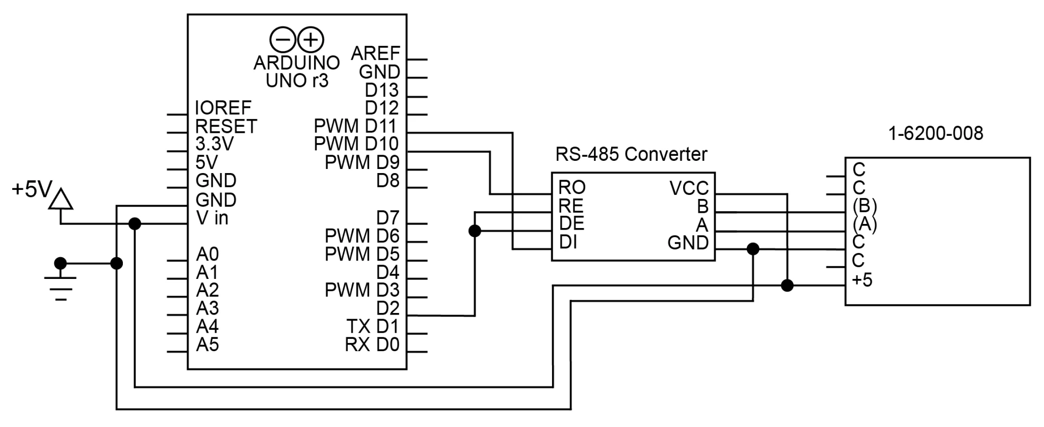
Figure 6 Schematic for connecting 1-6200-008 to Arduino with RS-485. RS-485 converter used as intermediary
The RS-485 commands used to communicate with the signal conditioner use the following format:
*xxyy#
The * is the start character, which begins each command. xx is the address the command is being sent to. By default, this will be 99 on the 1-6200-008. yy is the command itself. The # signals the end of the command. For example, the command to read the x axis tilt on address 99 is *9911#. All available commands can be found on the 1-6200-008 datasheet.
With the RS-232 to RS-485 converter inline, these commands can be sent to the converter with RS-232. The converter will then send them to the signal conditioner with RS-485. The setup function will be the same as it was for the RS-232 signal conditioner. The code below shows how this configuration can be used to read data from the signal conditioner:
// x axis tilt
    digitalWrite(9, HIGH); // enable transmission
    Sensor.print("*9911#"); // send x axis command
    digitalWrite(9, LOW); // enable reception
    delay(25); // wait for sensor to respond
    b = 0;
    while (Sensor.available()) {
        x[b++] = Sensor.read(); // store response in a char array
    }

    // y axis tilt
    digitalWrite(9, HIGH); // enable transmission
    Sensor.print("*9921#"); // send y axis command
    digitalWrite(9, LOW); // enable reception
    delay(25);
    b = 0;
    while (Sensor.available()) {
        y[b++] = Sensor.read(); // store response in char array
    }

    // temperature
    digitalWrite(9, HIGH); // enable transmission
    Sensor.print("*9941#"); // send temperature command
    digitalWrite(9, LOW); // enable reception
    delay(25);
    b = 0;
    while (Sensor.available()) {
        temperature[b++] = Sensor.read(); // store response
    }
Like with RS-232, the response will be a character array terminated by a new line and carriage return. If you would like to treat the array as a string, you will have to append the null character (‘\0’).
Addressed RS-485
It is possible to connect up to 32 1-6200-008 signal conditioners to a single bus. The signal conditioners can then be assigned addresses, providing a way for each sensor to determine whether to respond. Note that it is important to avoid connecting multiple sensors with the same address, as the sensors will interfere with each other’s transmissions.
By default, the address of the signal conditioner will be 99. To change it, make sure it is the only connected device with that address. Then, use the command *xx81Azz#, where xx is the current address and zz is the new address. For example:
Sensor.print("*9981A01#"); // change address from 99 to 01
Once the address has been changed, you will not be able to access the sensor using commands that start with 99 anymore. Instead, the new address 01 will replace the 99 in all commands. For example, the command to read product info would change from *9980# to *0180# after running the command above.
Once each sensor has been assigned a unique address, they can be attached to the circuit. Each signal conditioner can connect to the same bus with no additional components or connections. See figure 7 for a schematic showing this. 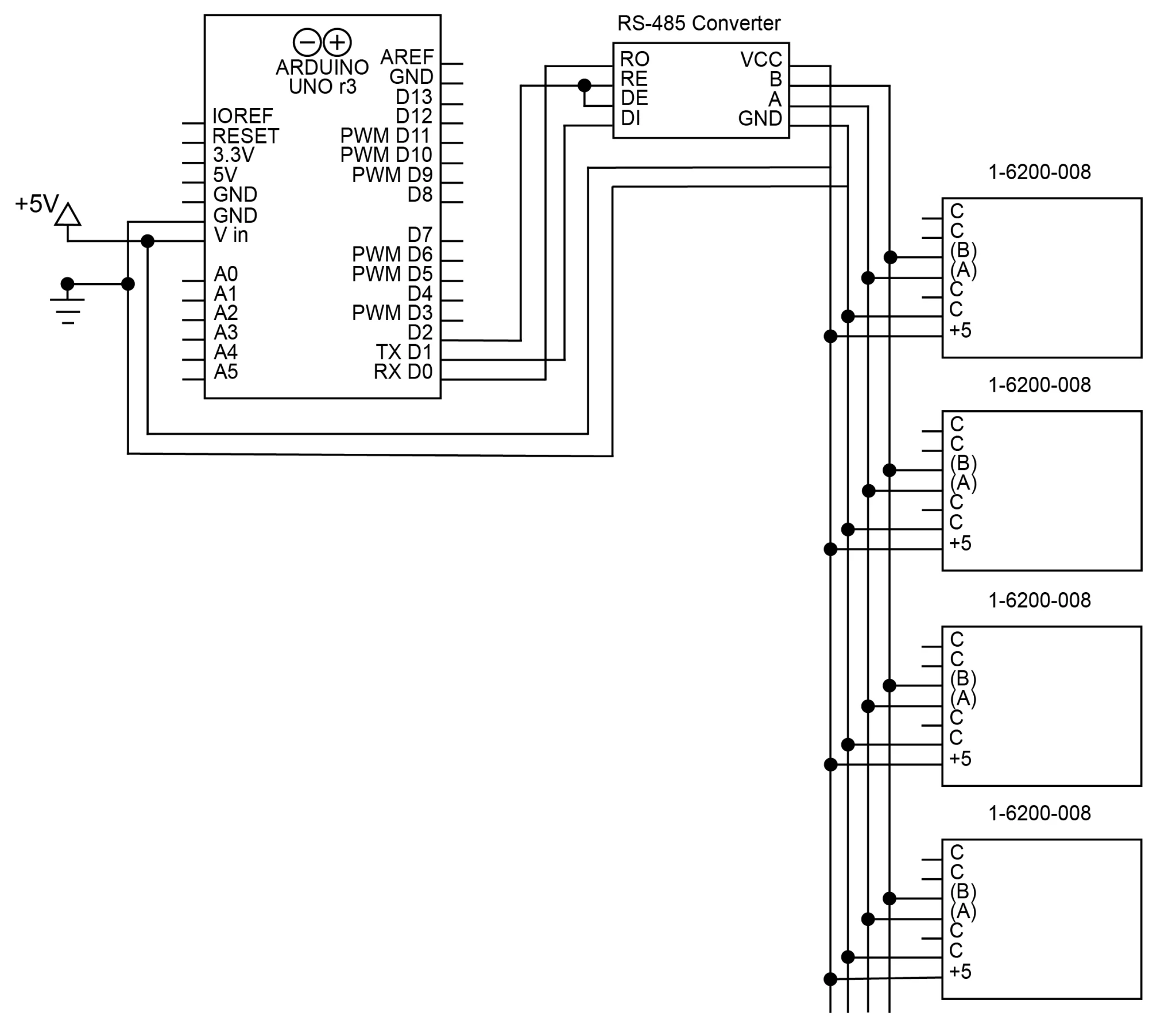
Figure 7 Schematic for connecting (4) 1-6200-008 signal conditioners to an Arduino with RS-485
An example of a program reading from multiple addressed RS-485 sensors is given below. This code is written for a circuit connected to 4 sensors, addressed 8 – 11.
char addr[4][3] = {"08", "09", "10", "11"};
for (int i = 0; i < 4; i++) { // run this code for every address
    // x axis tilt
    digitalWrite(9, HIGH); // enable transmission
    sprintf(cmd, "*%2s11#", addr[i]); // create x axis command
    Sensor.print(cmd); // send x axis command
    digitalWrite(9, LOW); // enable reception
    delay(25); // wait for sensor to respond
    b = 0;
    while (Sensor.available()) {
        x[b++] = Sensor.read(); // store response from sensor in a char array
    }

    // y axis tilt
    digitalWrite(9, HIGH); // enable transmission
    sprintf(cmd, "*%2s21#", addr[i]); // create command
    Sensor.print(cmd); // send command
    digitalWrite(9, LOW); // enable reception
    delay(25);
    b = 0;
    while (Sensor.available()) {
        y[b++] = Sensor.read(); // store response
    }

    // temperature
    digitalWrite(9, HIGH); // enable transmission
    sprintf(cmd, "*%2s41#", addr[i]); // create command
    Sensor.print(cmd); // send command
    digitalWrite(9, LOW); // enable reception
    delay(25);
    b = 0;
    while (Sensor.available()) {
        temperature[b++] = Sensor.read(); // store response
    }
}
The responses will be 8-byte character arrays containing the ASCII characters for a 16-bit number.