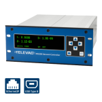
Description
This application note explains the process for downloading an Electronic Data Sheet (EDS) file to a Rockwell Automation Allen-Bradley CompactLogix Programmable Logic Controller (PLC). The EDS file contains all of the vendor and module
information for the EthernetIP networking device, as well as a complete list of Class 3 parameters and Class 1 connection information. A PLC operator can then use the file to look up data variable link paths, sizes, and data
types, and establish desired connections for operation.
Please see the MX200 Instruction Manual for a full description on Class 1 and Class 3 connections, and a complete ADI table including data instance, name, array length, access, and description, and for information on
configuring the IP Address.
Loading the EDS File
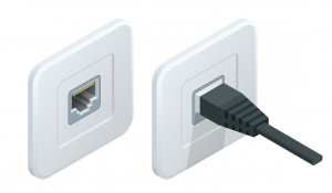
1. Connect the MX200 EthernetIP port on the back of the unit to your PLC.
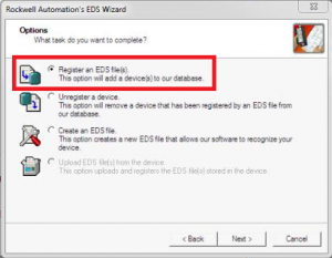
2. Using Rockwell Automation’s EDS Wizard, import the EDS file by selecting Tools → EDS Hardware Installation Tool.
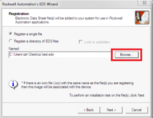
3. Browse to locate the EDS file. Before completing this step, be sure that the file “Televac_MX200_Ethernetip.eds” has been downloaded. Once the EDS file has been loaded, click Next.
4. Verify the file installation test results
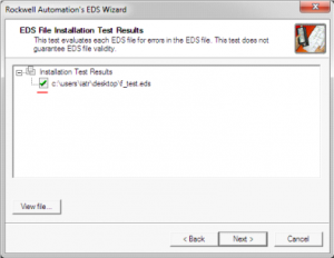
5. If desired, change the icon for the module, then click Next.
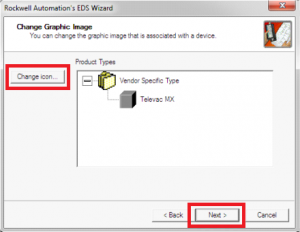
6. If desired, change the icon for the module, then click Next.
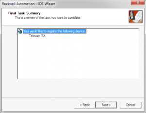
7. Click Finsh.
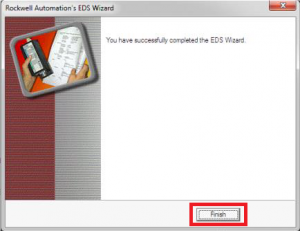
8. To update the file in the future, the file must first be unregistered. Then follow steps 1 through 7.
Setting up a Connection
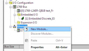
1. Add the new module to the network. To do this, right click on Ethernet → New Module.
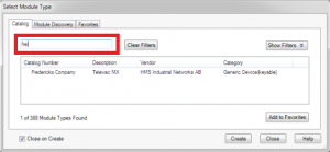
2. Find the module by typing “fredericks” into the search bar. Select the Televac MX module.
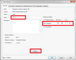
3. Set the device Name and IP Address, and then click Change module definition.
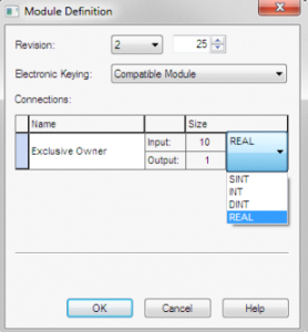
4. Set the data type to real.
5. You should now be able to establish connections to the data variables provided within the EDS. Refer to the EthernetIP for MX200 Instruction Manual for a more information related to setup and operation.
Electronic Keying Mismatch
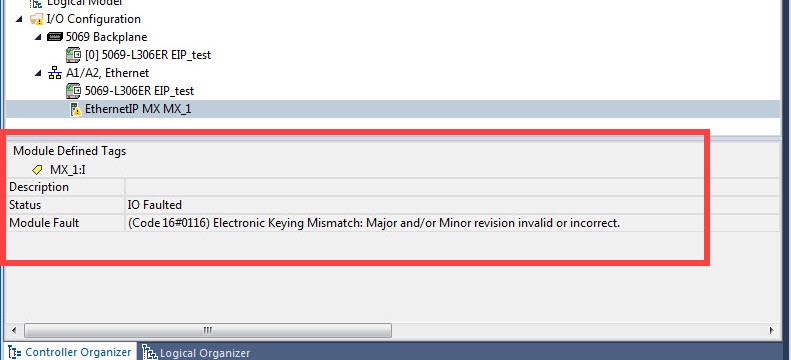
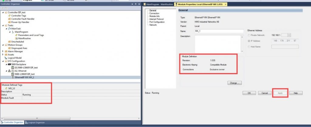
1. Verify that there is an error code identifying an Electronic Keying Mismatch
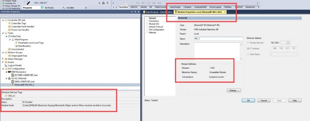
2. Open the module properties to display the Module Definition information
3. Using the web browser, identify the firmware revision level of the module
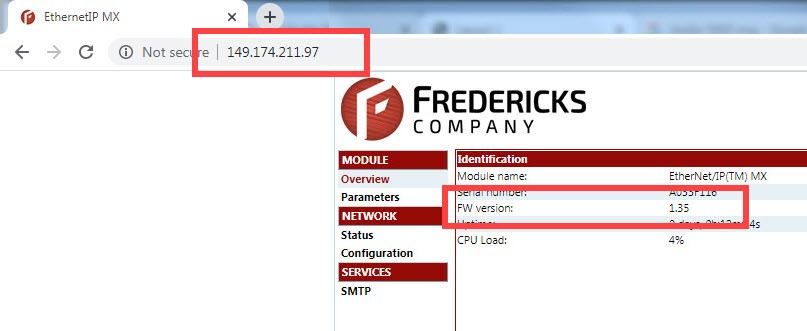
4. Using the web browser, identify the firmware revision level of the module
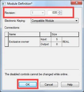
5. Select Apply and verify that the system connects and is running
Related Products
MX200 EthernetIP Vacuum Controller
• 1*10-11 Torr to 1*104 Torr
• Control up to 10 Televac® vacuum gauges
• EthernetIP/USB digital communications
• Easy-to-read OLED display


