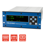
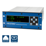
Beschreibung
This application note explains the process for interfacing and communicating with an MX200 from a Windows PC. The serial communications program Tera Term must be installed prior to following these instructions. If you don’t have Tera Term installed, click here to install the latest version from GitHub.
Anweisungen
1. Connect the MX200 USB port on the back of the unit to a USB port on your PC.
2. Drivers should automatically download and install. If not, the drivers can be downloaded here.
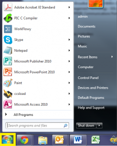
3. Open the Start Menu.
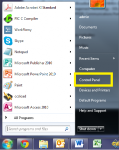
4. Open the Control Panel.
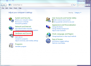
5. Open the Hardware and Sound.
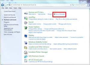
6. Open the Device Manager.
7. Expand the Ports (COM & LPT) drop down.
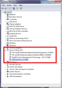
8. Determine the COM port assignment for your MX200, in this example the MX200 is assigned to COM3.
9. Open TeraTerm.
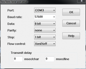
10. Open the Setup menu and select the Serial port… option.
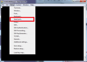
11. Change the Port setting to the COM port for your MX200, in this example it is COM3.
12. Ensure that the remainder of the settings match what is shown below, then select OK. Note that this example uses the default baud rate of 57600. This can be changed through the front panel by pressing the home button then going to Global Setup>Communications>Settings>Baud Rate.
- Baudrate: 57600
- Daten: 8 Bit
- Parität: keine
- Stopp: 1 Bit
- Flusssteuerung: Xon/Xoff
- Sendeverzögerung: 0 msec/Zeichen, 0 msec/Zeile
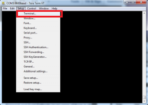
13. Open the Setup menu and select the Terminal setup… option.
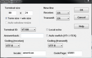
14. Ensure that the settings are the following based on how you’ll be using the communications, then select OK:
Zum Booten
- Empfangen: CR
- Übertragen: CR
- Lokales Echo: nicht angehakt
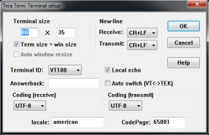
Für die Standardkommunikation im Terminal
-
- Empfangen: CR+LF
- Übertragen: CR+LF
- Lokales Echo: geprüft
15. You should now be able to communicate with the MX200. As an example, send the following command to read the output from all connected channels: “S1<cr>” (not including the quotations). A list of all commands can be found below in Table 1. A more detailed description of the communications can be found in the MX200 manual.
| Befehl | Beispiel Ausgang | Beschreibung |
| R1<cr> | XX<cr><lf> | Gibt Einheiteneinstellung XX aus: PA=Pascal, TR=Torr, MB=mBar, TD=Torr dezimal, MT=mTorr/Torr |
| W1XX<cr> | XX<cr><lf> | Einheiten auf XX einstellen: PA=Pascal, TR=Torr, MB=mBar, TD=Torr dezimal |
| S1XX<cr> | ppsee<cr><lf> | Der Vakuum-Messwert für Station XX ist ppsee |
| S1<cr> | XX=ppsee … XX=ppsee<cr><lf> | Ausgabe der ppsee-Messwerte für jeden Kanal XX |
| S2<cr> | NNNNNN<cr><lf> | Logik-Firmware-Version |
| S3<cr> | NNNNNN<cr><lf> | Firmware-Version anzeigen |
| S4<cr> | XX=YY … XX=YY<cr><lf> | Ausgabestationstypen: XX = Stationsnummer, YY = Sensortyp |
| S5<cr> | XX=YY … XX=YY<cr><lf> | Ausgangssollwert XX Status YY (ON=ein, OF=aus, 00=kein Sollwert angeschlossen) |
| S6<cr> | Televac … <cr><lf> | Alle Setup-Informationen ausgeben |
| RC1XX<cr> | Baa<cr><lf> | Ersten Kalibrierpunkt für Kanal XX ausgeben |
| RC2XX<cr> | Baa<cr><lf> | Zweiten Kalibrierpunkt für Kanal XX ausgeben |
| RC3XX<cr> | Baa<cr><lf> | Dritten Kalibrierpunkt für Kanal XX ausgeben, Fehler zurückgeben, wenn Punkt nicht vorhanden |
| RC4XX<cr> | Baa<cr><lf> | Vierten Kalibrierpunkt für Kanal XX ausgeben, Fehler zurückgeben, wenn Punkt nicht vorhanden |
| WC1XXBaa<cr> | PPSEE<cr><lf> | Ersten Kalibrierpunkt für Kanal XX setzen |
| WC2XXBaa<cr> | PPSEE<cr><lf> | Zweiten Kalibrierpunkt für Kanal XX setzen |
| WC3XXBaa<cr> | PPSEE<cr><lf> | Dritten Kalibrierpunkt für Kanal XX setzen, Fehler zurückgeben, wenn Punkt nicht existiert |
| WC4XXBaa<cr> | PPSEE<cr><lf> | Vierten Kalibrierpunkt für Kanal XX setzen, Fehler zurückgeben, wenn Punkt nicht existiert |
| R2<cr> | 01 02 03 04 05 … <cr><lf> | Gibt die an den MX200 angeschlossenen Kanalnummern aus |
| R3XX<cr> | HI<cr> or LO<cr><lf> | Gibt die HI/LO-Auflösung für Station XX aus |
| W3XX<cr> | HI<cr> or LO<cr><lf> | Umschalten der HI/LO-Auflösung für Station XX |
| R4<cr> | 01 02 03 04 05 … <cr><lf> | Gibt die Kanalnummern aus, die zur Anzeige auf dem Messbildschirm eingestellt sind |
| W4XX<cr> | ON<cr> or OF<cr><lf> | Fügt dem Messbildschirm den Kanal XX hinzu oder entfernt ihn |
| R5XX<cr> | FbaaBAA<cr><lf> | Analoges Ausgangsformat, hohe und niedrige Werte ausgeben |
| W5XXF<cr> | F<cr><lf> | Analoges Ausgangsformat für Kanal XX auf linear-dekadisch einstellen (lin/dec=3, lin/dec 7E=4) |
| W5XX1baa<cr> | Fbaa<cr><lf> | Analoges Ausgangsformat von Kanal XX auf linear einstellen: baa=hoher Wert |
| W5XX2baaBAA<cr> | FbaaBAA<cr><lf> | Analoges Ausgangsformat von Kanal XX auf linear einstellen: Baa=hoher Wert, BAA=niedriger Wert |
| R6XX<cr> | GG<cr><lf> | Ausgangsgaseinstellung für Kanal XX |
| W6XXGG<cr> | GG<cr><lf> | Kanal XX auf Gasart auf GG einstellen |
| R7Y<cr> | ppseePPSEEZZ<cr><lf> | Ausgangsrelais Y ein = ppsee, Relais Y aus = PPSEE, und Kanal ZZ dem Relais Y zugeordnet |
| W7YppseePPSEEZZ<cr> | ppseePPSEE<cr><lf> | Stellen Sie Relais Y ein auf ppsee, Relais Y aus auf PPSEE und Relais Y auf Kanal ZZ |
| R8<cr> | A<cr><lf> | Gibt den Kaltkathodenmodus aus, A (auto = 1, self = 2) |
| W8A<cr> | A<cr><lf> | Stellt den Kaltkathodenmodus ein, A (auto = 1, self = 2) |
| R9<cr> | BB<cr><lf> | Gibt den Kaltkathoden-Schaltpunktwert zurück, BB (01 bis 50) |
| W9BB<cr> | BB<cr><lf> | Stellt den Kaltkathoden-Schaltpunktwert ein, BB (01 bis 50) |
| R10<cr> | CD<cr><lf> | Liefert den Kaltkathodenstatus ungerade und gerade (ein/aus) C-ungerade, D-gerade (0 = aus, 1 = ein) |
| W10CD<cr> | CD<cr><lf> | Setzt den Kaltkathodenstatus ungerade und gerade (ein/aus) C-ungerade, D-gerade (0 = aus, 1 = ein) |
| C1TTTT<cr> | TTTT<cr><lf> | Baudrate auf TTTT einstellen |
| C2EE<cr> | EE<cr><lf> | Adresse auf EE (00 bis 99) einstellen, nur RS-485 |
| C4N<cr> | N<cr><lf> | I/O auf N ändern (RS-232=1, RS-485=2, USB=3) |
| C1<cr> | TTTT<cr><lf> | Einstellung der Ausgangs-Baudrate |
| C2<cr> | EE<cr><lf> | Ausgangsadresse für RS-485 |
| C4<cr> | N<cr><lf> | Art der Ausgangskommunikation (RS-232=1, RS-485=2, USB=3) |
| HM<cr> | M<cr><lf> | Rückkehr zum Messbildschirm |
| RLR<cr> | SXXX<cr> | Ausgabe der Leckratenberechnung oder Kanal 1 in mTorr (S=Vorzeichen, XXX=-999 bis 999) |
| WLRX<cr> | X<cr><lf> | Einschalten oder Ausschalten der Leckratenberechnung für Kanal 1 (0=aus, 1=ein) |
| WD_1XX<cr> | XX<cr><lf> | Wiederherstellen der Standardwerte für die Kanaleinstellung für Kanal XX |
| WD_7X<cr> | X<cr><lf> | Sollwertrelais-Standardwerte für Sollwert X wiederherstellen |
| WD_CXX<cr> | XX<cr><lf> | Kalibrierungs-Standardwerte für Kanal XX wiederherstellen |
| WD_G<cr> | D<cr><lf> | Standardwerte für globale Einstellungen wiederherstellen |
| SN<cr> | NNNNNN<cr><lf> | Gibt die sechsstellige Seriennummer des Geräts zurück, mit Werten von 000000 bis 999999 |
| PG_LGC<cr> | Bootloader … <cr><lf> | Ruft den Bootloader für die Logik-Firmware auf |
| PG_DSP<cr> | Bootloader … <cr><lf> | Ruft den Bootloader für die Display-Firmware auf |
Verwandte Produkte
- 1*10-11 Torr bis 1*104 Torr
- Steuerung von bis zu 10 Televac® Vakuummessgeräten
- Digitale RS-232/RS-485/USB-Kommunikation
- Leicht ablesbares OLED-Display
MX200 EthernetIP Vakuum-Controller
- 1*10-11 Torr bis 1*104 Torr
- Steuerung von bis zu 10 Televac® Vakuummessgeräten
- Digitale EthernetIP/USB-Kommunikation
- Leicht ablesbares OLED-Display


