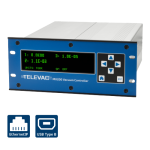
Description
This application note explains the process for the setup, configuration, and troubleshooting of a Televac® EthernetIP device. In order to communicate with the unit, the EthernetIP device’s IP address will need to be configured to the same network as the PLC. The following steps describe how to establish the initial connection, and what steps to follow should any issues arise. The first setup option assumes internet connectivity and makes use of an IP address configuration utility tool for the module. If an internet connection is not available, refer to the Setup and Troubleshooting Guide for Televac®️ EthernetIP Option 2.
Please see the EthernetIP for MX200 User Manual for a full description on Class 1 and Class 3 connections, and a complete ADI table including data instance, name, array length, access, and description. Please see Application Note 3016 for downloading an Electronic Data Sheet (EDS) file to a PLC.
1. Installing the Ipconfig Tool
1.1 IPConfig is a utility tool provided by HMS that is designed to work with the incorporated EthernetIP networking module for ease of setup. To install the tool, download and install the “IPConfig Utility” package under the Software section from the following site:
https://www.anybus.com/support/file-doc-downloads/compactcom-40-series-specific/?ordercode=AB6604
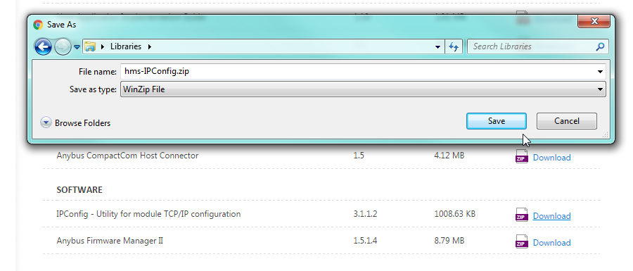
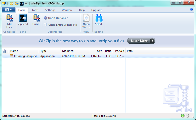
1.2 Save the file to the computer, and then open the folder and run IPConfig Setup.exe. Install the IPConfig program.
2. Windows 10 Operating Systems Configuration
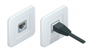
2.1 Connect the MX200 EthernetIP port on the back of the unit to your computer.
2.2 In order to configure the IP address of the unit to the network, the network address and subnet masks must be known. If this information is already available, skip to step 2.5 to use the IPConfig utility to set the module IP address. If not, open the cmd terminal from the Start Menu.
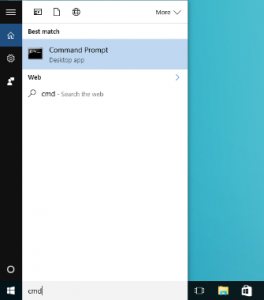
2.3 In the terminal, run the command “ipconfig” to see the network settings.
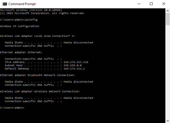
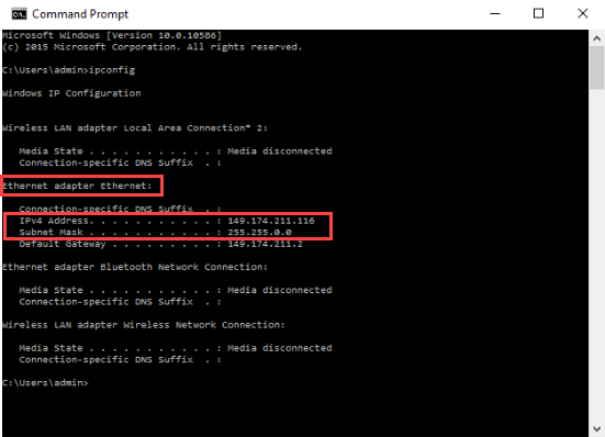
2.4 Find the “Ethernet adapter Ethernet”, and mark down the IPv4 Address and Subnet Mask. This will be the network to assign to the unit. In order to communicate on the network properly, a different IP address on the network that is not in use by any other device will be needed. IT help may be needed to verify at this step; if the unit IP address conflicts with any other device on the network the unit will not communicate.
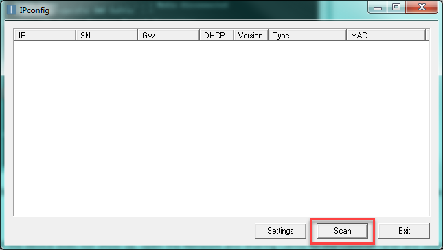
2.5 Run the IPConfig utility downloaded from HMS. Once open, scan the network to find the device.
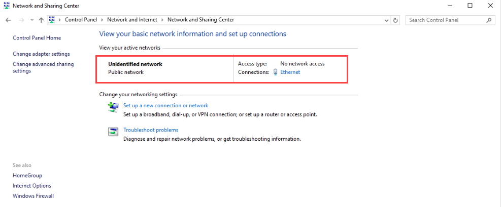
2.6 If the device does not show up, open the Network and Sharing Center in the Control Panel and verify that an Ethernet connection is being made. If there is no connection, check the cable and reinsert the Ethernet cable into the adapter on the computer.
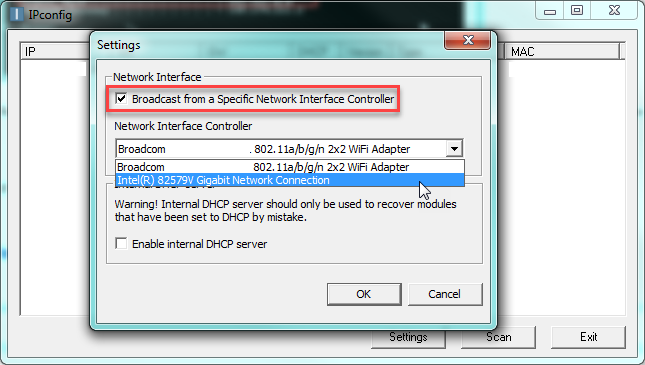
2.7 In the IPConfig utility, select settings, and then check the box for Broadcasting from a Specific Network Interface Controller, and select the Ethernet controller.
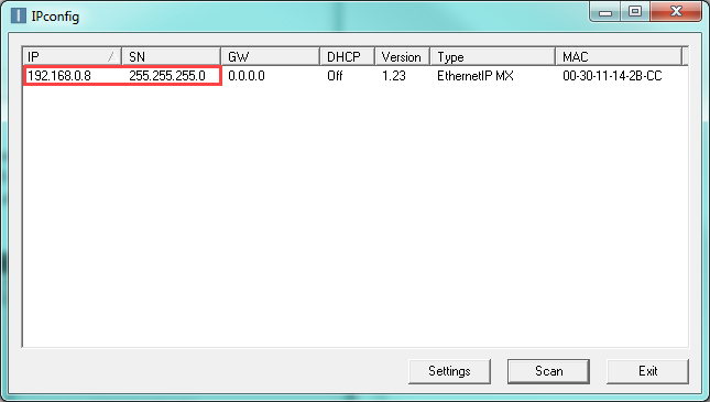
2.8 You should now be able to see the device with the default IP address 192.168.0.8 and subnet mask 255.255.255.0.
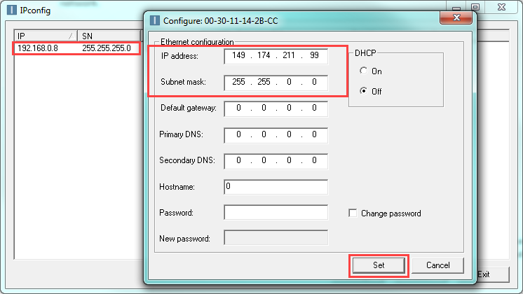
2.9 Select this device to change the settings. In this example, the terminal revealed in step 3.1.4 that the network needed is 149.174.211.X with a subnet mask of 255.255.0.0. The device will be set to 149.174.211.99 with a subnet mask of 255.255.0.0. This example IP address was verified to not conflict with any other devices on the local network. Once changes to the settings are complete, select Set. Select Scan to refresh the list.
2.10 If DHCP is used, the IP address will be assigned automatically, but could be changed by the DHCP server. If a connection is made to a static IP address from a PLC to a device with a DHCP-assigned IP address, it will need to be verified and potentially modified before use.
3. Verifying the Setup
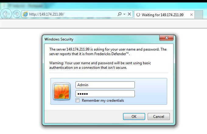
3.1 After the IP address and subnet mask are configured, network connectivity can be verified through the PLC or through the web functionality. To verify through the web functionality, type the IP address into address bar in the browser and enter the username and password (default Admin:admin).
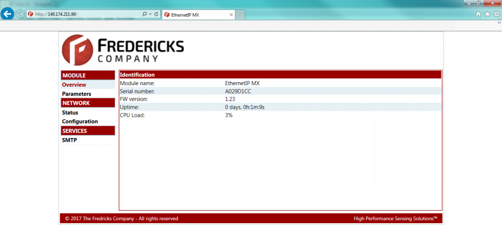
3.2 If the unit is connected to the network properly, the web page should be displayed. From here, data parameters can be viewed and changed along with current EthernetIP network settings.
3.3 The unit should now be ready to use with a PLC. Please refer to Televac®️ Application Note 3016 for downloading the Electronic Data Sheet (EDS) and creating a connection.
Related Products
MX200 EthernetIP Vacuum Controller
• 1*10-11 Torr to 1*104 Torr
• Control up to 10 Televac® vacuum gauges
• EthernetIP/USB digital communications
• Easy-to-read OLED display


