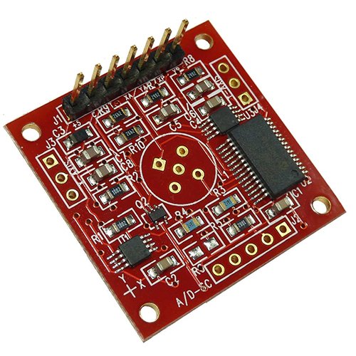
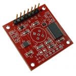
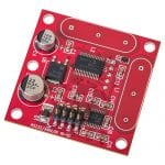
Part Number: 1-6200-007
Kompatibel mit: Alle elektrolytischen Neigungssensoren von Fredericks
Merkmale und Vorteile:
- Kleiner elektronischer Neigungssensor
- Analog 0 to 5 V DC and PWM outputs for simple integration
- Befestigungslöcher und Anschlüsse für einfache Integration
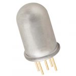
- Sensoren der Serie 0717 können direkt auf der Platine montiert werden
- Die Sensoren der Serie 0703 können extern montiert und mit Drähten verbunden werden
| Schnittstelle | Analog 0 to Vdd and PWM |
| Auflösung des Analogeingangs | 16 Bit (10 Bit überabgetastet) |
| Betriebsbereich | 0% bis 100% des Sensorbereichs |
| Versorgungsspannung | 3,3 V DC bis 5 V DC |
| Versorgungsstrom | 15 mA @ 5 V DC, 10 mA @ 3.3 V DC |
| Betriebstemperatur | -40 °C bis 85 °C |
| Lagertemperatur | -40 °C bis 125 °C |
| Gesteuerte Sensoren | 1 oder 2 |
| Achsen der Messung | 1 oder 2 |
| Bereich des Temperatursensors | -40 °C bis 125 °C |
| Gehäuse | Keine |
| Elektrische Anschlüsse | 7 Stifte, 2,54 mm (0,1") Abstand |
| Gewicht | 4 g |
| Länge | 32 mm (1,25") |
| Breite | 32 mm (1,25") |
| Bohrung Mitte | 27 mm (1,05") |
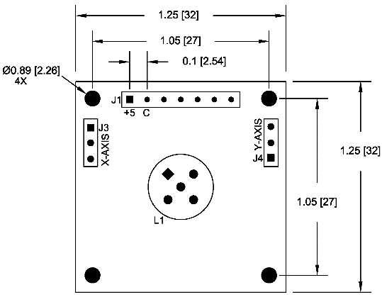
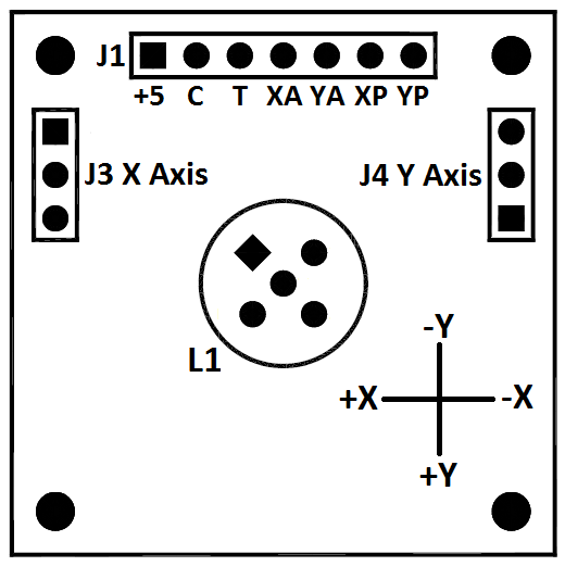
| J1 Stift 1 (+5) | Supply (+, Vdd) |
| J1 Stift 2 (C) | Supply (-, Vss) |
| J1 Pin 3 (T) | Temperature analog output (0 to Vdd) |
| J1 Pin 4 (XA) | X axis analog output (0 to Vdd) |
| J1 Pin 5 (YA) | Y axis analog output (0 to Vdd) |
| J1 Pin 6 (XP) | X axis PWM output |
| J1 Pin 7 (YP) | Y axis PWM output |
| L1 | Zweiachsiger Sensoranschluss |
| J3 | Einzelachsensensor x-Achsenanschluss |
| J4 | Einachsensensor y-Achsenanschluss |
Analoger Ausgang Beschreibung
| Vdd = 3.3 V DC | 0 V DC to 3.3 V DC, 0° tilt = 1.65 V DC |
| Vdd = 5.0 V DC | 0 V DC bis 5 V DC, 0° Neigung = 2,50 V DC |
PWM Output Description
| Frequency | 122 Hz |
| Duty Cycle | 1% to 99%, 0° tilt = 50% duty cycle |
| Auflösung | 16 Bits |
Note that the analog output is integrated from the PWM output and this circuit will be sensitive to moisture. An enclosure or conformal coating may be necessary in higher humidity environments.
| RoHS-konform |
Produkt-Dokumentation
| 1-6200-007 Datenblatt |
| 1-6200-007 STEP File |
| Arduino Analoge Kommunikation INO-Datei |
| Arduino PWM-Kommunikation INO-Datei |
Anwendungshinweise
Werkzeuge
| Winkelmessungs-Konverter |
Videos
| Was ist ein elektrolytischer Neigungssensor? |
Broschüren
| Neigungsmessung Produktkatalog |
STEP-Datei herunterladen
| Teilenummer | Beschreibung | STEP-Datei |
| 1-6200-007 | Analog/PWM Signal Conditioner | Herunterladen |
1-6200-007 Quantity Discounts
| Menge | Preis |
| 1 | $69.13 |
| 10 | $65.30 |
| 100 | $58.75 |
| 500 | $47.24 |
| 1000+ | $41.98 |


