


Descrizione
Questa nota applicativa illustra le basi del processo di creazione e mappatura delle connessioni di Classe 3 Explicit Message nell'ambiente di sviluppo Rockwell Automation Studio 5000 per i controllori logici programmabili (PLC) CompactLogix. Ciò consentirà al PLC di comunicare con il dispositivo EthernetIP Televac® collegato per scambiare dati e impostare parametri da una postazione remota. Prima di impostare una nuova connessione, consultare la Nota applicativa Televac® 3016 per caricare un file EDS nel PLC e aggiungere un nuovo modulo Ethernet al progetto.
Per una descrizione completa delle connessioni di Classe 1 e Classe 3, nonché per una tabella ADI completa che include istanza di dati, nome, lunghezza dell'array, accesso e descrizione, e per informazioni sulla configurazione dell'indirizzo IP, consultare il relativo Manuale di istruzioni del prodotto Televac® EthernetIP.
1. Impostazione di una connessione GET di Classe 3
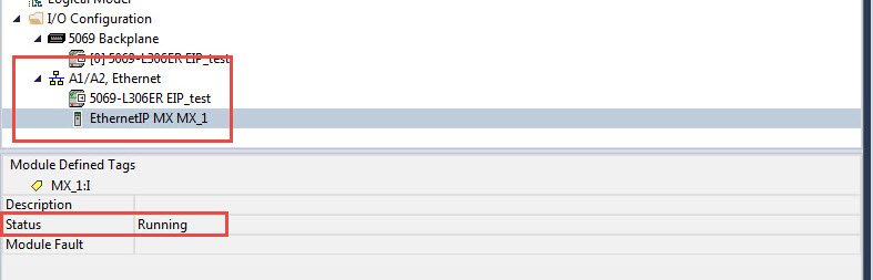
1.1. Verificare che il file EDS sia stato caricato e che un modulo Ethernet sia stato aggiunto al progetto.
1.2. Selezionare il rung per il messaggio, fare clic con il pulsante destro del mouse e selezionare "Aggiungi elemento ladder..." dal menu a discesa.
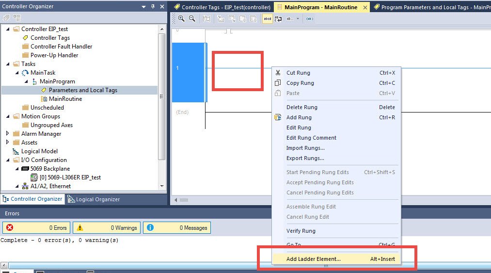
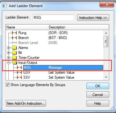
1.3. Individuare la cartella "Input/Output" e selezionare "MSG" dall'elenco.

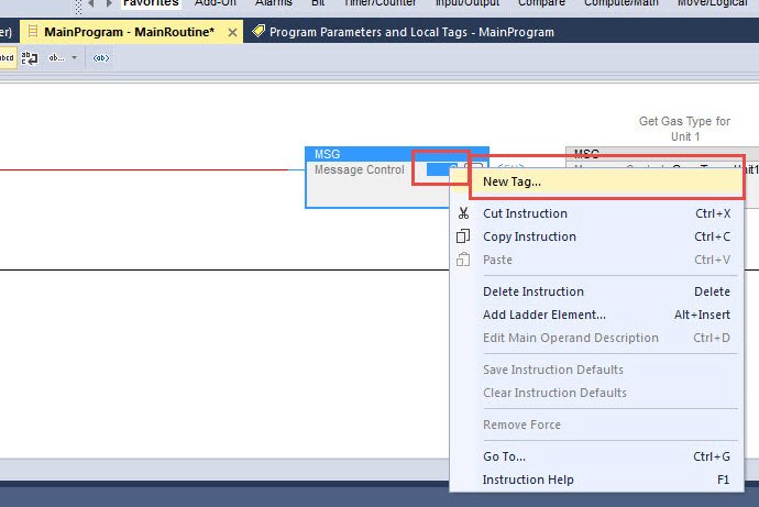
1.4. Fare clic con il tasto destro del mouse sulla casella dell'elemento MSG e selezionare "Nuovo tag..." dal menu.
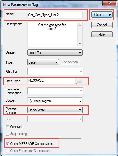
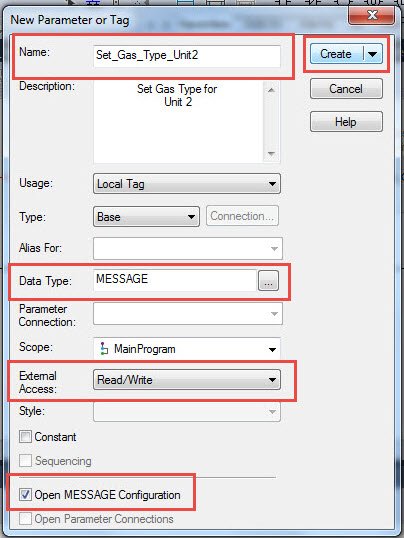
1.5. Fornire un nome per il tag, selezionare il tipo di dati MESSAGE, impostare l'accesso esterno in base all'ADI del manuale e selezionare Apri configurazione MESSAGE. Una volta completato, selezionare Crea.
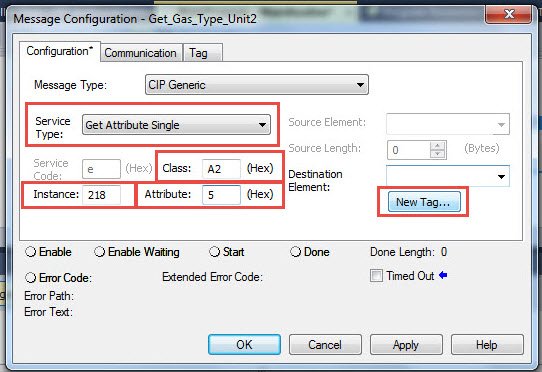
1.6. Selezionare "Ottieni attributo singolo" dall'elenco Tipo di servizio. Impostare Classe su "A2" e Attributo su "5". Questi valori saranno gli stessi per tutte le connessioni Televac® EthernetIP di Classe 3. Fare riferimento alla tabella ADI del prodotto appropriato che si trova nel Manuale d'uso dell'istanza. In questo esempio, il tipo di gas per l'unità 2 del gateway EthernetIP è l'istanza 218. Selezionare "New Tag..." per l'elemento di destinazione in cui i dati saranno memorizzati localmente.
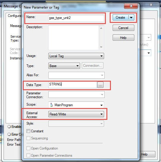
1.7. Creare un nuovo tag locale per memorizzare i dati dei parametri. I dati di pressione vengono trasmessi come REAL e tutti gli altri dati come STRING. Impostare l'accesso esterno in base alle informazioni GET/SET dell'ADI riportate nel manuale. Una volta completato, selezionare Crea.
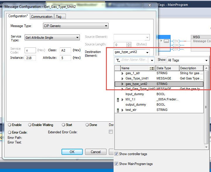
1.8. Selezionare il tag locale appena creato nella casella Elemento di destinazione.
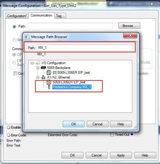
1.9. Passare alla scheda Comunicazione e selezionare il modulo Televac Ethernet. Verificare che il nome del modulo compaia nella posizione Path.
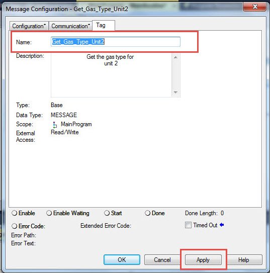
1.10. Passare alla scheda Tag e verificare che il Nome del tag corrisponda al tag creato al punto 1.5. Al termine, selezionare Applica per salvare le modifiche e OK per uscire dal configuratore.
2. Impostazione di una connessione SET di Classe 3
2.1. Verificare che il file EDS sia stato caricato e che un modulo Ethernet sia stato aggiunto con successo al progetto.

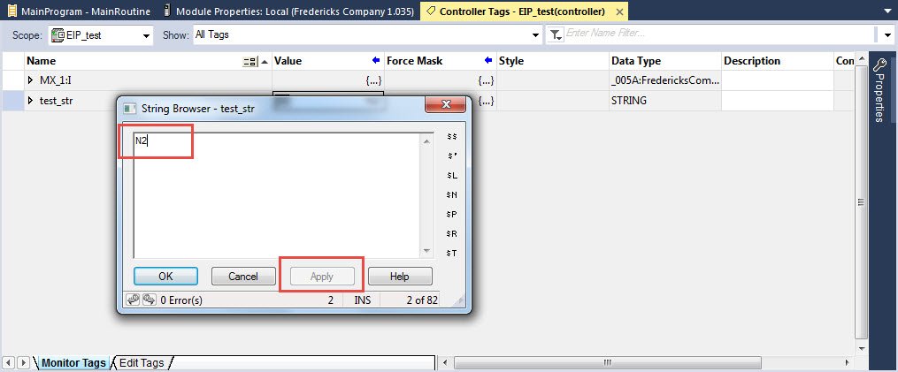
2.2. Creare un nuovo tag di tipo STRING nella tabella Controller Tags. Impostare la lunghezza della stringa in modo che corrisponda alla dimensione dell'array dell'istanza impostata dalla tabella ADI del prodotto. In questo esempio, la dimensione dell'array del tipo di gas del gateway EthernetIP è di 2 byte.

2.3. Impostare la stringa sul parametro desiderato. In questo esempio, la stringa è impostata su "N2" per il gas azoto.
2.4. Selezionate il rung per il messaggio, fate clic con il pulsante destro del mouse e selezionate "Aggiungi elemento ladder..." dal menu a discesa.

2.5. Individuare la cartella "Input/Output" e selezionare "MSG" dall'elenco.
2.6. Fare clic con il tasto destro del mouse sulla casella dell'elemento MSG e selezionare "Nuovo tag..." dal menu.

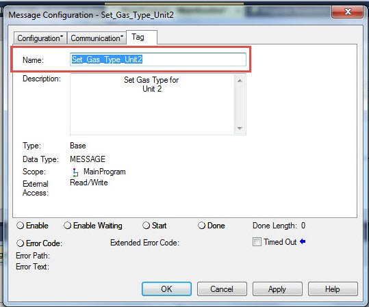
2.7. Fornire un nome per il tag, selezionare il tipo di dati MESSAGE, impostare l'accesso esterno in base all'ADI del manuale e selezionare Apri configurazione MESSAGE. Una volta completato, selezionare Crea.
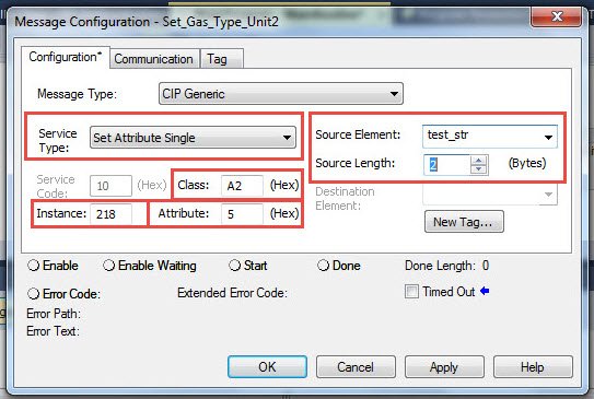
2.8. Selezionare "Imposta attributo singolo" dall'elenco Tipo di servizio. Impostare la classe su "A2" e l'attributo su "5". Questi valori saranno gli stessi per tutte le connessioni Televac® EthernetIP di Classe 3. Fare riferimento alla tabella ADI del prodotto appropriato che si trova nel Manuale d'uso dell'istanza. In questo esempio, il tipo di gas per l'unità 2 per il gateway EthernetIP è l'istanza 218. Impostare l'elemento sorgente e la lunghezza sul tag creato al punto 2.2, utilizzato per memorizzare il valore da inviare al modulo.
2.9. Spostarsi sulla scheda Communication e selezionare il modulo Televac Ethernet. Verificare che il nome del modulo compaia nella posizione Path.

2.10. Passare alla scheda Tag e verificare che il Nome del tag corrisponda al tag creato al punto 2.7. Al termine, selezionare Applica per salvare le modifiche e OK per uscire dal configuratore.
2.11. L'elemento ladder SET MSG dovrebbe ora essere pronto a inviare dati al modulo Ethernet.
Prodotti correlati

Controllore di vuoto MX200 EthernetIP
- Da 1*10-11 Torr a 1*104 Torr
- Controllo di un massimo di 10 misuratori di vuoto Televac
- Comunicazioni digitali EthernetIP/USB
- Display OLED di facile lettura