


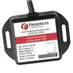
Part Number: 0729-1753-99
Features and Benefits:
- ±60° operating range, ±25° linear range inclinometer
- Dual/two-axis measurement inclinometer
- Simple to use analog 0 to 5 V DC and PWM output inclinometer
- Response time of ≤250 ms high precision inclinometer sensor
- Works with industry-standard 12 V DC vehicle batteries
- Low current device drawing 20 mA at 12 V DC; low power consumption
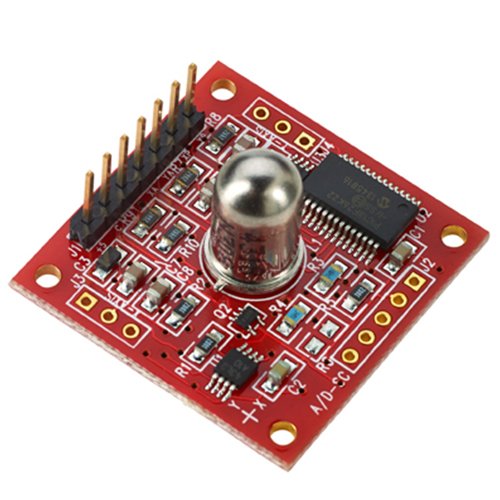
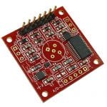
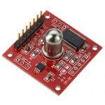
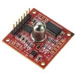
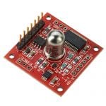
- PCB board-level design for simple integration
- Superior performance in extreme temperatures and environments
- Excellent customer support
Product Description
Price
Quantity
| Interface | Analog 0 to Vdd and PWM |
| Supply Voltage (Vdd) | 3.3 V DC to 5 V DC |
| Supply Current | 15 mA (5 V DC), 10 mA (3.3 V DC) |
| Analog Input Resolution | 16 bits (10 bits oversampled) |
| Operating Range | ±60º |
| Linear Range | ±25º |
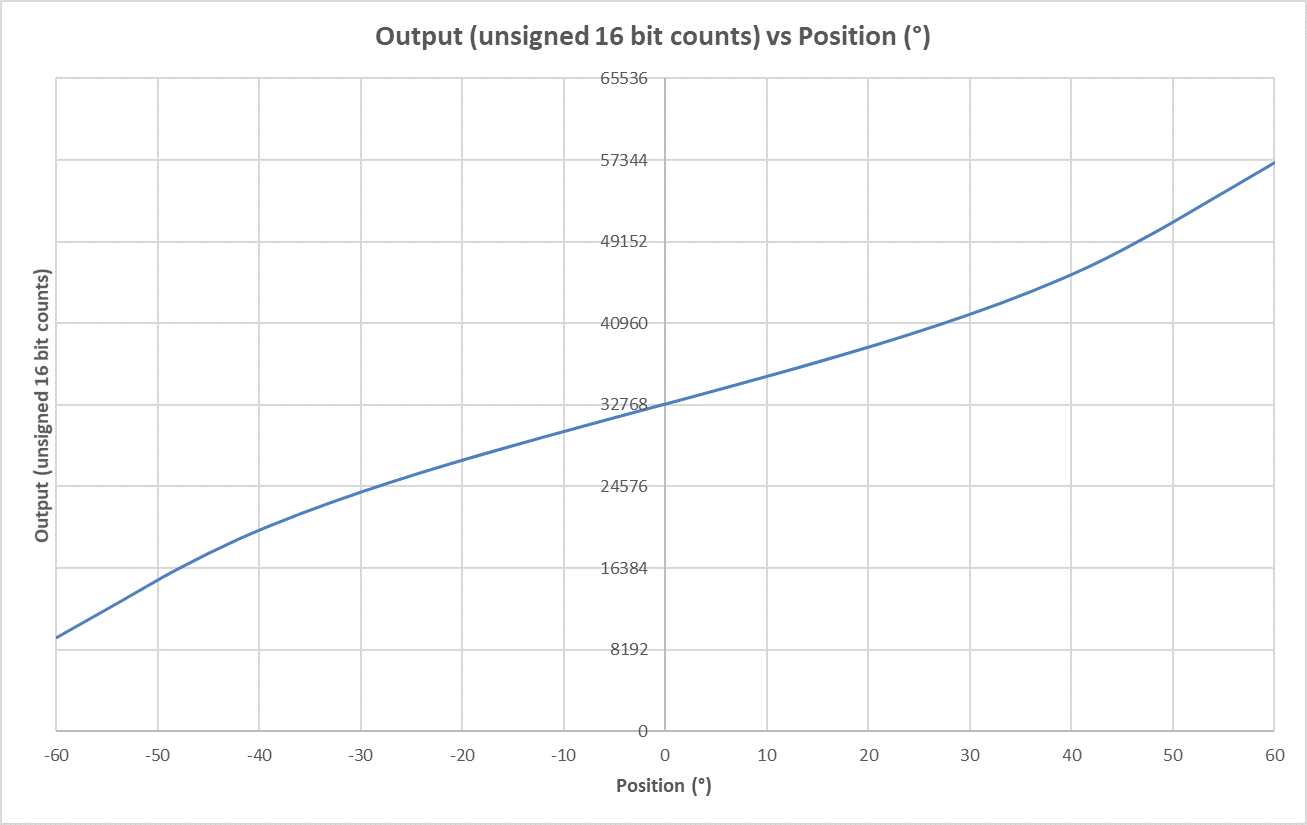
| Typical Output Behavior | View on office.com | Download (.xlsx) |
| Axes of Measurement | 2 |
| Repeatability | ±0.1° |
| Resolution | ≤0.003° |
| Null Offset | ±5° |
| Long Term Stability/Drift | ≤0.1° |
| Null Temperature Coefficient | ≤0.006° per °C |
| Scale Temperature Coefficient | 0.1% per °C |
| Materials | Contains magnetic metals |
| Operating Temperature | -40 °C to 85 °C |
| Storage Temperature | -40 °C to 125 °C |
| Temperature Sensor Range | -40 °C to 125 °C |
| Time Constant (63.2% of output) | ≤250 ms |
Operating Range
| Housing | None (PCBA) |
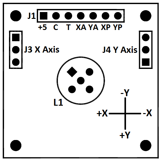
| Electrical Connections | 7 Pin, 2.54 mm (0.1”) spacing |
| Weight | 5.5 g |
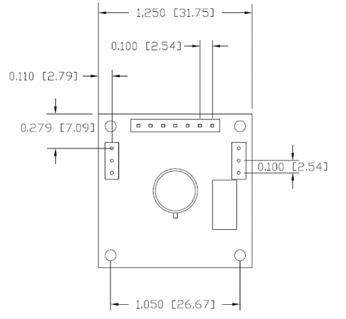
| Length | 31.75 mm (1.25”) |
| Width | 31.75 mm (1.25”) |
| Height | 16.10 mm (0.63”) |
| Hole Center | 26.67 mm (1.05”) |
| J1 Pin 1 (+5) | Supply (+, Vdd) |
| J1 Pin 2 (C) | Supply (-, Vss) |
| J1 Pin 3 (T) | Temperature analog output (0 to Vdd) |
| J1 Pin 4 (XA) | X axis analog output (0 to Vdd) |
| J1 Pin 5 (YA) | Y axis analog output (0 to Vdd) |
| J1 Pin 6 (XP) | X axis PWM output |
| J1 Pin 7 (YP) | Y axis PWM output |
| L1 | Dual axis sensor connection |
| J3 | Single Axis sensor x axis connection |
| J4 | Single axis sensor y axis connection |
Analog Output Description
| Vdd = 3.3 V DC | 0 V DC to 3.3 V DC, 0° tilt = 1.65 V DC |
| Vdd = 5.0 V DC | 0 V DC to 5 V DC, 0° tilt = 2.50 V DC |
PWM Output Description
| Frequency | 122 Hz |
| Duty Cycle | 1% to 99%, 0° tilt = 50% duty cycle |
| Resolution | 16 bits |
Note that the analog output is integrated from the PWM output and this circuit will be sensitive to moisture. An enclosure or conformal coating may be necessary in higher humidity environments.
| RoHS Compliant |
Product Documentation
| 0729-1753-99 Datasheet |
| 0717-4318-99 Typical Output Behavior: View on office.com | Download (.xlsx) |
| 0729-1753-99 STEP File |
| Arduino Analog Communications INO File |
| Arduino PWM Communications INO File |
Application Notes
Tools
| Angle Measurement Converter |
Videos
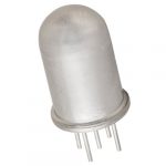
| What Is An Electrolytic Tilt Sensor? |
Brochures
| Tilt Measurement Product Catalog |
Download STEP File
| Part Number | Description | STEP File |
| 0729-1753-99 | ±60° Analog/PWM Inclinometer | Download |


0729-1753-99 Quantity Discounts
| Quantity | Price |
| 1 | $84.29 |
| 10 | $78.89 |
| 100 | $70.82 |
| 500 | $63.15 |
| 1000+ | $61.23 |