


Part Number: 1-6200-007
Compatible With: All Fredericks electrolytic tilt sensors
Features and Benefits:
- Small size electronic tilt sensor
- Analog 0 to 5 V DC and PWM outputs for simple integration
- Mounting holes and connectors for simple integration
- 0717 series sensors can be mounted directly on the board
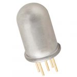
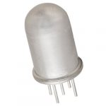
- 0703 series sensors can be mounted externally and connected with wires
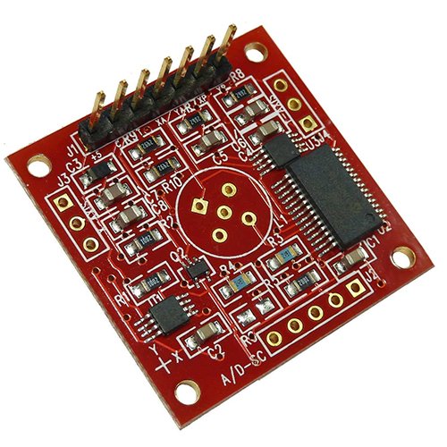
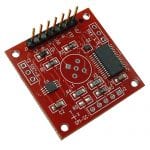
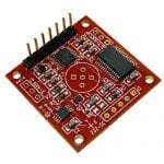
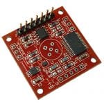
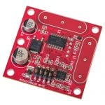
All Fredericks electrolytic tilt sensors require a basic electrolytic tilt sensor circuit to generate a tilt angle output. These are often called signal conditioners, signal conditioning boards, or electronic tilt sensors. The 0717 series dual/two-axis tilt sensors can be mounted directly on these boards for a complete inclinometer solution. Other single/one axis 0703 series and glass tilt sensors must be mounted externally and connected with wires.
This electrolytic tilt sensor circuit has analog 0 to 5 V DC and PWM outputs and mounting holes, making it simple to integrate into your own design. If you’re looking to integrate the electrolytic tilt sensor circuit PCB into your design, The Fredericks Company can help. We offer bills of material, Gerber files, firmware source files, and engineering support. Our team includes electrical/hardware, firmware, and mechanical design engineers ready to assist you. To request information or support, please complete the Technical Support form, including details about your application and specific needs.
| Interface | Analog 0 to Vdd and PWM |
| Analog Input Resolution | 16 bits (10 bits oversampled) |
| Operating Range | 0% to 100% of sensor range |
| Supply Voltage | 3.3 V DC to 5 V DC |
| Supply Current | 15 mA @ 5 V DC, 10 mA @ 3.3 V DC |
| Operating Temperature | -40 °C to 85 °C |
| Storage Temperature | -40 °C to 125 °C |
| Sensors Controlled | 1 or 2 |
| Axes of Measurement | 1 or 2 |
| Temperature Sensor Range | -40 °C to 125 °C |
| Housing | None |
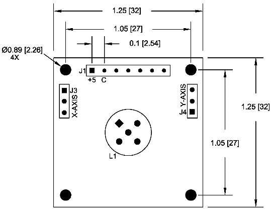
| Electrical Connections | 7 Pin, 2.54 mm (0.1") spacing |
| Weight | 4 g |
| Length | 32 mm (1.25") |
| Width | 32 mm (1.25") |
| Hole Center | 27 mm (1.05”) |
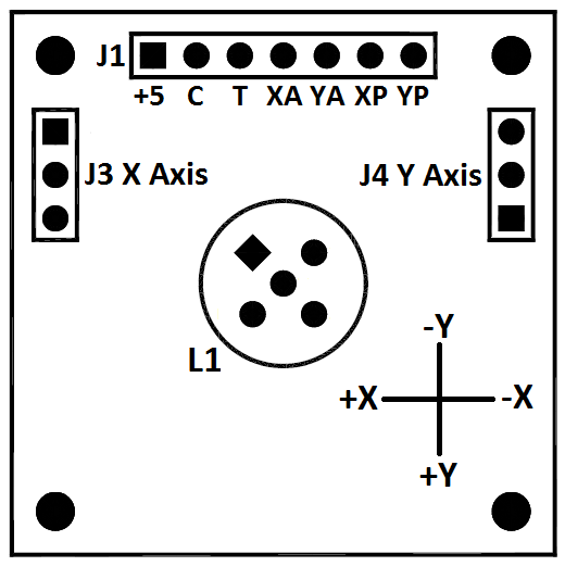
| J1 Pin 1 (+5) | Supply (+, Vdd) |
| J1 Pin 2 (C) | Supply (-, Vss) |
| J1 Pin 3 (T) | Temperature analog output (0 to Vdd) |
| J1 Pin 4 (XA) | X axis analog output (0 to Vdd) |
| J1 Pin 5 (YA) | Y axis analog output (0 to Vdd) |
| J1 Pin 6 (XP) | X axis PWM output |
| J1 Pin 7 (YP) | Y axis PWM output |
| L1 | Dual axis sensor connection |
| J3 | Single Axis sensor x axis connection |
| J4 | Single axis sensor y axis connection |
Analog Output Description
| Vdd = 3.3 V DC | 0 V DC to 3.3 V DC, 0° tilt = 1.65 V DC |
| Vdd = 5.0 V DC | 0 V DC to 5 V DC, 0° tilt = 2.50 V DC |
PWM Output Description
| Frequency | 122 Hz |
| Duty Cycle | 1% to 99%, 0° tilt = 50% duty cycle |
| Resolution | 16 bits |
Note that the analog output is integrated from the PWM output and this circuit will be sensitive to moisture. An enclosure or conformal coating may be necessary in higher humidity environments.
| RoHS Compliant |
Product Documentation
| 1-6200-007 Datasheet |
| 1-6200-007 STEP File |
| Arduino Analog Communications INO File |
| Arduino PWM Communications INO File |
Application Notes
Tools
| Angle Measurement Converter |
Videos
| What Is An Electrolytic Tilt Sensor? |
Brochures
| Tilt Measurement Product Catalog |
Download STEP File
| Part Number | Description | STEP File |
| 1-6200-007 | Analog/PWM Signal Conditioner | Download |


1-6200-007 Quantity Discounts
| Quantity | Price |
| 1 | $72.60 |
| 10 | $68.60 |
| 100 | $61.70 |
| 500+ | Request a Quote |