


What’s the difference between an accelerometer and a tilt sensor?
Terminology surrounding tilt sensors can be confusing, and some of the most common questions we hear are “what’s the difference between an accelerometer and an inclinometer?” and “can I use an accelerometer as a tilt sensor?”.
TLDR: Accelerometers are sometimes used to measure tilt, but they are often unreliable (for tilt measurement) in end uses where vibration is present. They also can wear out because they have moving parts, which causes output drift over time. Another common issue is turn-on bias, resulting in low repeatability and low accuracy tilt measurements.
In this post we’ll provide a quick explanation to help you as you shop for the right sensor for your application.
What is an accelerometer?
Accelerometers measure, you guessed it, acceleration! But they’re also used to measure vibration, shock, and tilt (inclination). Accelerometers measure tilt by looking at the acceleration they experience from earth’s gravity (~9.8 m/s2 for those of us that haven’t been in school for a while). They give the most reliable measurements when the object they’re attached to isn’t moving, so accelerometers are often used in tandem with other sensors, like gyroscopes, to correct for these errors.
MEMS (Micro-Electro Mechanical System) based accelerometers are the most common used for tilt measurement because of their small size, low cost, and relative ease of integration.
What is an inclinometer?
There are many different types of inclinometers (also called tilt sensors), from low accuracy mechanical ball bank and bubble sensors, to higher accuracy liquid capacitive and extremely sensitive force balanced sensors. Like MEMS accelerometers, MEMS inclinometers are popular for many of the same reasons (small size, low cost, simple integration), but because MEMS technology relies on moving parts, they tend to wear out much faster than their fluid-based electrolytic counterparts.
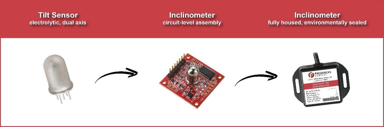
Fredericks’ electrolytic tilt sensors are resistive fluid-based devices, meaning the sensor provides an output voltage proportional to the tilt angle of the sensor with reference to gravity (based on the position of the fluid). A typical tilt sensor has multiple stationary electrodes that extend into the fluid, and the position is measured by the resistance of the fluid between them.
The sensor is mounted onto a PCB, or printed circuit board, and the sensor output is connected to an ADC, or analog to digital converter. The reading from the ADC is processed by a microcontroller and turned into a user friendly output, and this whole assembly is what we at Fredericks call an inclinometer.
Pros and cons of accelerometers for tilt measurement
The key advantages of using accelerometers for tilt measurement are that they’re relatively inexpensive, small in size, and often come packaged in a convenient way (think surface mount and pick-and-place), which makes them an attractive option for commercial applications.
The trade off is that they’re less accurate because they’re designed to measure acceleration. In order to get the same accuracy as an electrolytic tilt sensor, the cost would of an accelerometer increases dramatically, and there are still issues with output drift and hardware breakdown over time because of the moving parts.
Understanding the different factors of accuracy
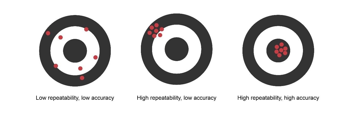
Below is a diagram that represents the relationship between repeatability and accuracy. From the diagram you’ll see that if something (like a tilt sensor or an inclinometer) isn’t repeatable, it also can’t be accurate. There are other factors that influence accuracy, particularly linearity.
In embedded systems where sensors are often used, it’s common that memory and processing speed are limited. Ideally you’d have a sensor with a linear output, allowing you to use a linear conversion (which requires the least memory and speed, and is the simplest to implement).
In reality most sensors have a non-linear output, so it can be a little challenging to convert the output to a usable value, particularly in an embedded system. There are ways of dealing with non-linear outputs, two of which are to use piecewise linear interpolation (also called a lookup table) or polynomial interpolation, both of which require significantly more memory and speed.
Due to variations from sensor to sensor in their non-linear output, individual calibration is sometimes required. Oh and don’t forget about temperature characterization, turn-on bias, and drift. The bottom line is that high accuracy can be hard to achieve.
Applications where electrolytic tilt sensors leave accelerometers in the dust
For industrial applications like RV leveling and construction vehicle safety, electrolytic tilt sensors and inclinometers are often a much better option than MEMS accelerometers.
Looking for a tilt sensor? Check out our product selection guide or talk with one of our applications engineers today and find out how Fredericks inclinometers and tilt sensors deliver high repeatability and accuracy without breaking the bank. Use our online chat or email us at sales@frederickscompany.com and we’ll get back to you in less than 24 hours.
Related Products


±60° operating range, ±0.1° accuracy
Dual (Two) Axis High Precision Digital Inclinometer
±50° operating range, ±20° linear range
Dual-Axis Electrolytic Tilt Sensor
±60° operating range, ±20° linear range
Dual (Two) Axis High Precision Digital Inclinometer
±60° operating range, ±0.1° accuracy
Dual (Two) Axis Analog Inclinometer